
PixelCNC v1.70b
This version of PixelCNC includes a number of additions, changes, and bug fixes, as per usual! The most notable addition is a new built-in interactive tutorial system that enables us to script tutorials for walking users through the use of different features and functionality, and through the process of creating different types of projects and effects, all right within PixelCNC itself!
We've also upgraded the canvas/simulation rendering to mitigate the rendering artifacts that are inherent to the rendering technique used, as well as improved the usability of several functions. The most prominent changes and additions to PixelCNC v1.70b are detailed below.
Interactive Tutorials
We've added a new tutorial system into PixelCNC to serve as a means of providing built-in help to users directly in the interface. This allows us to (relatively) quickly script tutorials that walk users through how to use PixelCNC and its different features and functionality. Users can now learn kinesthetically right in the software, rather than trying to follow and replicate what someone is doing at their own speed in a video. The new tutorial system can be accessed via the Help menu and directly from the View Toolbar next to the canvas undo/redo buttons:

When the tutorial system is accessed users are shown a dialog listing all of the available tutorials. Selecting a tutorial displays a description for the tutorial below the tutorials list:

After selecting a tutorial the user clicks 'Start'. This will prompt the user asking whether or not they wish to start the tutorial because the currently open project will be discarded as a demo project used by the tutorial will be opened.

When a tutorial is active an overlay is included at the bottom of the 3D view for displaying the current tutorial step. This includes a body of text and potentially an image too. Tutorial steps instruct the user as to what's to be done for that step and/or provide explanations about a parameter or function. The tutorial overlay is not a typical PixelCNC dialog that can be moved around.
At the bottom of the tutorial overlay are Prev/Next buttons for moving between the steps of the tutorial. Included between them is a readout to show the current step and total number of steps in the current tutorial to serve as a sort of progress indicator. A button captioned 'Done' on the exits the tutorial.

A tutorial step can highlight a UI element, such as a parameter, button, or menu. This is to help the user navigate the interface, guiding them to where their attention should be. If the step does not highlight any UI element then it will resort to highlighting the next step button instead, indicating that the user must progress the tutorial by clicking it. Otherwise the tutorial is automatically progressed to the next step when the user interacts with the highlighted UI element.
We hope this system helps new users get up to speed quicker with how PixelCNC does things and how they can use it to do the things they wish. There may even be a thing or two that existing users could learn from the tutorials that this update includes. Right now only 5 tutorials are included to premiere the new tutorial system but they do cover a wide array of topics, features, functions, and their usage. Let us know what else we should create tutorials about by sending us an email at: support@deftware.org.
We're also looking into using this new system to develop simple walkthrough 'wizards' that break down creating certain project types into a series of steps, like creating a V-carving from a user-supplied image or vector, for instance (Zero2CAM style).
Isolated Layer Tracing
The Trace-to-Paths function has been changed to automatically update the canvas rendering in the 3D view to include only the active layer being traced, regardless of its blend mode, Z-Fill, and any other layers that are included with it in the canvas composition that the currently selected layer group produces. In other words: when the Trace-to-Paths function is used with a raster/model/text layer selected, the canvas is replaced with the active layer by itself so that the trace Z-plane properly depicts where the layer will be traced in the 3D view.

Raster-From-Paths Super Quality Option
The Stroke to Paths and Shapes From Paths functions for generating raster-layers containing 3D shapes and swept forms now includes a toggleable 'Super Quality' option at the bottom of each of their respective dialogs. This option doubles the resolution of the raster-layer that is generated, increasing the overall quality of generated shapes and their surfaces. This will incur about a quadrupling of the computation that's required to calculate the raster-layer's height values - and thus the time it takes to finish generating.

This option especially helps when a raster-layer is being generated from a paths-layer that is raised off the bottom of the canvas to include an extruded base of around the shapes to be generated. Enabling Super Quality will smooth out the vertical sides of the resulting base by creating a raster-layer that's at twice the heightmap resolution of the canvas.
Layer Group Changes
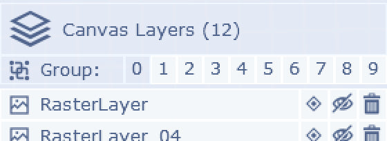
The number of canvas Layer Groups in a project has been increased from 8 groups to 10 groups. Their numbering has also been shifted down by 1. Instead of being numbered 1-10 they are now numbered 0-9, this is to keep their button labels at a single digit after adding the two extra layer groups. Existing project files with layers that belonged to group 1 will now belong to group 0, layers that belonged to group 2 now belong to group 1, etc...
Layer Groups now can include paths-layers as well as the other layer types. Previously, paths-layers could not be included in groups because they did not impact the canvas composition and the include/exclude toggle shown on layers was grayed out for paths-layers. They can now belong to layer groups and are hidden from the 3D view if they are not included in the active layer group. Operations that utilize a paths-layer as their contour input must have a layer group selected that the desired paths-layer to be used is included in. The only paths-layers that will be chooseable for an operation to generate cutpaths from are those that are included in the layer group that is chosen in the operation's parameters.
Invert Canvas Z-Plane Contour
Operation types that can use contour input from either a Z-plane contouring of the canvas or a paths-layer for generating toolpaths now allow inverting paths-layer input as can be done when using a canvas Z-plane contour input. The 'Invert' option swaps which areas of the contour input are considered 'inside' and 'outside', or 'islands' and 'pockets'. When contouring the canvas, the trace Z-plane that's shown intersecting the canvas in the 3D view is colored red for islands and green for pockets. In other words, green is the area to fill with cuts (as a general rule).

For the medial-axis carving operation this makes it quicker and easier to create a text-layer with the default Maximum blend mode on a canvas with a Z-fill set to the bottom of the canvas volume and still generate a V-carving toolpath that cuts inside the text-layer's contours without having to setup blending to form pockets from the text-layer first, for example.
When using a paths-layer as contour input its (closed) paths are treated as pockets by default, but this might not be the desired behavior. v1.70b now allows for inverting paths-layer contour input to cause PixelCNC to treat paths as islands inside of a canvas-sized pocket.
On a side note: paths are not all treated as either pockets or islands. Paths contained inside of other paths are treated as the opposite of whatever the path they're contained inside of is. e.g. a set of 3 concentric paths, with the invert option disabled, will treat the outer path as a pocket, the next one as an island, and the inner-most as another pocket. Enabling the invert option on an operation will swap this so that the outer-most becomes an island, the next inner one a pocket, and the inner-most an island.
High Quality Canvas/Simulation Rendering
The rendering method used for the canvas and (non-raymarched) simulation now includes improved overall quality, at the expense of a few more texture samples per pixel being performed on available graphics hardware. This rendering technique draws a stack of quadrilaterals along the dominant camera viewing axis, maximizing heightfield rendering performance across a wide range of hardware. This approach also minimizes the amount of compute work that's needed to both render and update the contents of the rendered heightfield.

The caveat is that this 'slice stack' rendering method can lead to distracting rendering artifacts where each slice is not only drawing the heightfield's surface but also some of the area beneath the heightmap, due to each slice having zero thickness and spacing between them. The camera can essentially peer between slices. This is further exacerbated when aliasing artifacts appear along heightfield discontinuities (i.e. vertical walls) particularly when zoomed out some.

v1.70b includes a new pixel shader that resolves the surface of the heightfield for the visible part of each quadrilateral 'slice' by performing a few extra texture samples that narrow down where the intersection between the camera and heightfield are. This is achieved by backtracking along a ray from the polygon surface toward the camera to refine the texture coordinate that ends up being used to sample the heightmap for calculating coloration and surface normals for calculating lighting. The end result improves quality well enough that the actual number of quads needed to render the heightfield has been reduced (the Canvas Geometry and Simulation Geometry settings found in their respective dialogs). There's no need to reduce these settings as we've already tuned how much geometry these settings result in for the visual fidelity improvement that the extra texture samples provide.
These changes to the canvas and simulation rendering do not mitigate the rendering artifacts that will still appear along the silhouette of their heightmaps. Thin geometry will still appear less than ideal, but the default PixelCNC settings shouldn't really have a problem. The GIFs shown above are with the Canvas Geometry setting toward the lowest setting purely for demonstrating the contrast between v1.69b and v1.70b's rendering fidelity.

Some users may experience a degradation in performance and 3D view responsiveness on their system due to the extra video memory bandwidth that's used by the new pixel shader. We've made sure to minimize the total number of extra texture samples this adds to reduce the impact on rendering speed that this visual quality improvement may cause. If the 3D view is still too slow and sluggish, such as on low-end netbooks and laptops, this new rendering technique can be toggled off via the 'High Quality Rendering' option that's been added to the View Settings dialog found under the Config menu.
Machine-Space Layer Origins
Since the introduction of the canvas system to PixelCNC with v1.34a the origin of layers has been in terms of the canvas volume. That is to say that a layer's origin has been relative to the bottom-front-left corner of the canvas, as though that were the origin of the canvas itself. This has made working with positioning layers require a bit more thought in some situations where spacings and positions are important to a project.
With the v1.70b update this has been changed to where layer origins are now relative to the machine origin that's shown as red/green/blue axis lines in the 3D view. This will not affect older project file versions as this is purely a UI change and not an actual modification to how layers are stored. Layer positions are still internally represented in canvas-space (relative to the bottom-front-left corner) but when displaying a layer's origin parameters this is automatically calculated to be relative to the machine origin, and vice-versa when the user enters a new layer origin.
This changes how layer origins are affected when the canvas dimensions are changed. When the canvas XY dimensions are changed, positions of layers will be retained relative to the machine origin. However, if the canvas Z size is changed, layers will retain their Z position relative to the bottom of the canvas. This behavior is preferable to what would otherwise occur if layer Z origins are retained relative to the machine origin, when the canvas Z size is changed. At least that's been our opinion. Let us know if you think otherwise!
Example Media

Returning back to PixelCNC's early days, a folder of example images is once again included with release builds and installed into PixelCNC's folder path. These are largely for creating tutorials that use known images for the user to learn how to use. We'd like to include 2D vector images, geometry, and 3D models too at some point in the future as well.
Unicode Filepath Compatibility
There has been a long standing issue with PixelCNC and its inability to read or write to any filepath that included non-ASCII characters. Those with Windows usernames that included characters with diacritics or non-English alphabet characters, for instance, would not be able to save or export anything to their user folder on their operating system. This also prevented PixelCNC from being able to output log files and save user configurations, which also led to activation with a product key not persisting between sessions.
We've implemented a solution that seems to resolve the situation. Users should now be able to load/save files in PixelCNC to filepaths that include unicode characters. However, non-ASCII characters will not be accepted by edit boxes in the UI for things like layer, operation, and tool names. It's also likely that text-layers cannot accept non-ASCII characters as well that are typed on the keyboard while text-editing mode is enabled.
PixelCNC Installer
For five years PixelCNC builds have been released as a downloadable ZIP file archive that users must manually extract/copy the contents of to somewhere on their computer in order to begin using the software. This meant that there was no automatic desktop shortcut creation, or PNC project file type association with the program itself. For v1.70b we're releasing PixelCNC with an installer to automate the addition of these convenient changes to users' systems.
Most web browsers are not keen on downloading executables that have not been digitally signed using a cryptographic certificate, which can only be issued by a central Certificate Authority, such as Verisign, GlobalSign, DigiCert, etc... Unsigned executables will cause browsers and operating systems (especially Windows) to interrupt users with all manner of warnings in an attempt to dissuade them from allowing such executables to run - which is fair in this day and age what with the multitude of nefarious types who actively abuse the trust of others.
Unfortunately, this is not very good for independent developers that are still trying to get their name out there. We've been working on acquiring a digital certificate which has proven to be more difficult than it is for most developers due to some unique circumstances that only a number of months-away scheduled in-person appointments can resolve (they're coming up soon!) Removing these 'unknown publisher' warnings is important for any software developer as they may scare away potential users, but we've been lucky enough that so many have both taken a chance on our unsigned CAM software and supported us by purchasing a product key. Thank you!
PixelCNC downloads will continue being released as a ZIP file download for now, but in the meantime they will now contain an EXE installer for user convenience. After we're able to digitally sign PixelCNC installers we will begin releasing them as a standalone download, and no longer rely on distributing PixelCNC via ZIP archives.
What's Next?
Users have reported that their non-QWERTY keyboard layouts are still treated like QWERTY keyboards in PixelCNC while entering text. We did attempt a fix a few versions ago that ended up not working out due to some API documentation errors, and it came to be that a proper fix will require a bit of an overhaul of the keyboard input system at the end of the day. We're working on it!
We're excited about the new tutorial system and want to hear what people would like to see included in there. Is there something you've wanted to know how to make using PixelCNC? Is there a certain geometry that you'd like to know how to produce for your projects? Confused about how a certain feature or function works? We want to know about it! Send us an email at support@deftware.org and let us know.
Thanks!